This page provides quick hints on how to get started with the web-based LC-3 simulator, developed by William Chargin. You can use the same simulator embeded in this site by clicking on "simulator" icon
(at top), or go directly to the original here (they are identical).
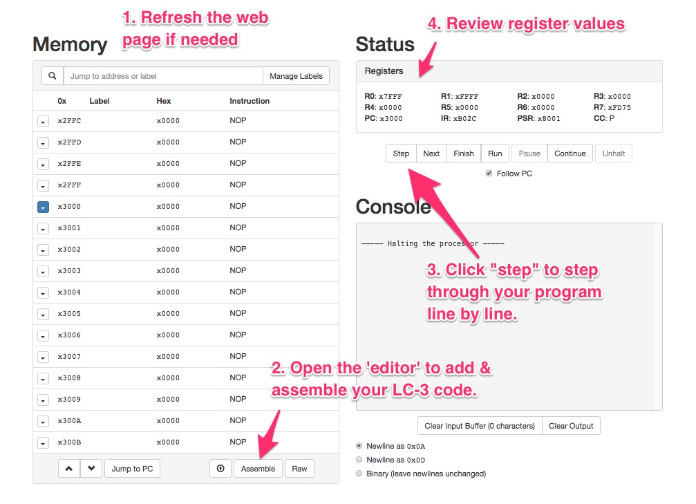
The Simulator runs in any web browser (requires no loading or installation), and has some great tools to help you get your work done quickly.
Step 1: Open Editor
After jumping to the Simulator page, click "ASSEMBLE" (at bottom) to open the LC-3 'text editor':
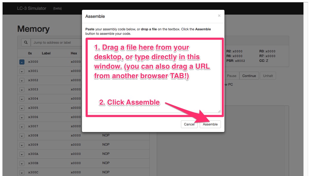
Step 2: Write & Assembly Code
After clicking "ASSEMBLE" on the home page of the simulator, you can type code from scratch, or paste, or drag/drop files ito the editor window. When you are ready, click the "Assemble" button at the bottom of the editor to see if you program builds properly:
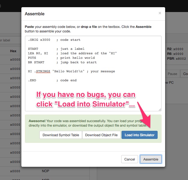
Step 3: Load Simulator:
If your code assembled correctly, you are ready to load it into the simulator and return to the simulator's main page to run your program"
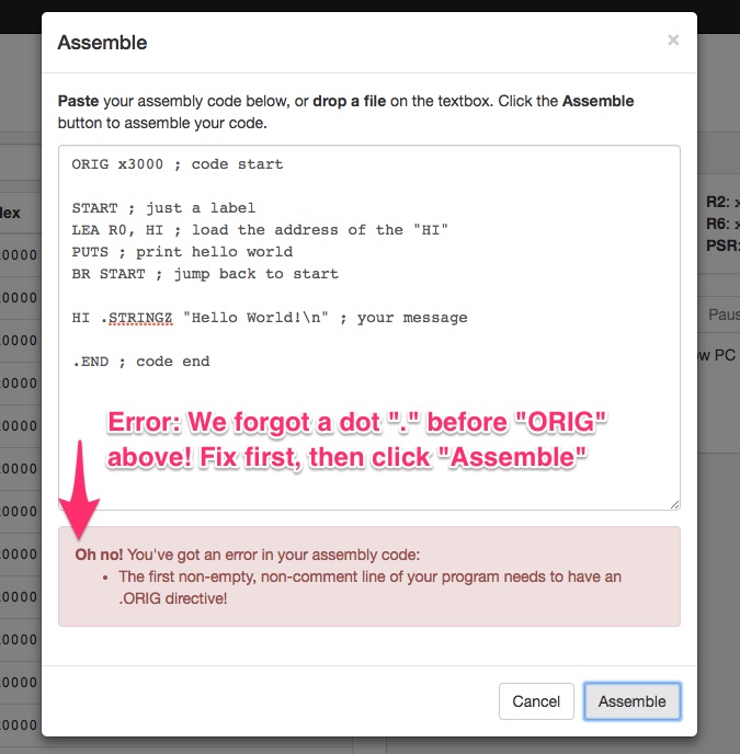
Step 4: Fix bugs:
If errors were detected in your code, review and try assembling again.
Step 5: Run your your code:
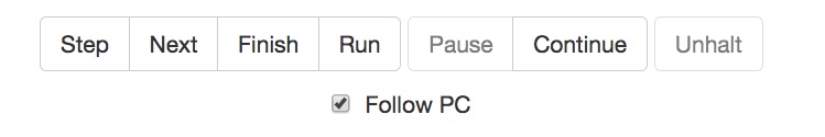
You have various options for running your code. Generally you will want to "step" or "next" through each line of your code when you are first getting started.
Step: steps through line by line - including System-level traps like PUTS and OUT, and subroutine calls. Might be too much.
Next: like Step, but 'skips over' function calls including system level traps. This means that subroutines ARE called, and program execution pauses when they return, allowing you to "next" or "step" again. Nice for keeping a high-level view of what's going, unless you are chasing a bug in one of your functions or some interaction with a trap or interrupt.
Finish: Finishes execution of the subroutine you are currently in. If you are in the main program, 'finish' will finish your program.
Run: Runs the program from the beginning until a HALT or .END is reached, or termination is forced in some other way. Otherwise, the program will run indefinitely, or until you hit "pause"
Pause: Pause execution of the program if it is currently running, preserving the current program counter so that you can step, next, continue, or run again.
Continue: Continue paused execution fromt he current program counter, like "run".
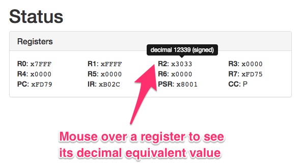
Step 6: Inspect registers:
Note that you can 'mouse over' any register shown above to see a tool tip that conveys the register's equivalent decimal value.
Registers R0 through R7 will report a 'signed value' decimal equivalent for each register.
This means the value interpreted from the two's complement notation will be reported.
Alternatively, the program counter (PC), IR and PSR will be reported as unsigned values, since they represent addresses.
! ×
Memory:
mc m+ m- mr
Credit: https://github.com/wchargin
Credit: https://github.com/evanw
Enter Circuit Logic Equation:
Result:
Available Input (for use in your equation above)
a =
b =
c =
d =
e =
f =
g =
LD ("Load Direct")
Reference
LD R#, address LD R0, LABEL
LD R0, #102
Load a specific register (R0-R7) with the CONTENTS at an address in memory.
The address may be represented by a LABEL, where LABEL is defined as follows:
LABEL .FILL x1234
In this case, the register will be loaded with the value x1234.
This value SITS AT an address (we do not really care which one) that has been tagged with LABEL.
LABEL tells LD know where to go to get a value.
Alternatively, an offset value can be specified instead of a label (#102 above). The offset is measured from the location of the LD command.
NOTE: The offset (via LABEL or numeric value) must be a 'short distance away' from LD, since it represents an offset distance to
'reach forward or backward' relative to the LD instruction,
(to x1234 in this case). To be specific, the distance from the actual
LD command to the LABEL cannot be more
than a a signed 9bit value (-256 <= distance <= 255)
LDI ("Load Indirect Addres")
Reference
LDI R#, address LDI R0, LABEL
LDI R0, #102
Get the address that is stored at LABEL (or an offset), and then get the VALUE at THAT address (this is the indirect part).
NOTE: The offset value cannot be bigger than a 9 bit signed value. Specifically -256 <= distance <= 255.
For a good sample on how to use the LDI opcode, please see the STI/LDI Example in the examples area.
LDR ("Load Relative")
Reference
LDR R#, R#, address LDR R0, R1, #4
Load register R0 with the VALUE AT the address in (R1 + (decimal value 4)).
That is, find the address by adding (R1+4), get the value at that address, and put it in R0.
NOTE: The offset value (#4 decimal above) cannot be bigger than a 6bit signed value.
Specifically -32 <= distance <= 31. So it is an even SHORTER jump than for the LD command which has 9bits available for the offset.
LEA ("Load Effective Address")
Reference
LEA R#, address
        LEA R0, LABEL

        LEA R0, #102
Load register R0 with the ADDRESS of LABEL (not its contents!). Often used with .STRINGZ and PUTS to print a string.
Alternatively, an offset value can be specified instead of a label (#102 above).
Note 1: Even if LABEL refers to a 'string of characters' in memory, we are still only loading the ADDRESS of LABEL into R0. Any subsequent PUTS (for example) will get the ADDRESS of the string from R0, and will print 'characters' starting at that address, until a null character is encountered.
Note 2: LABEL must be a 'short distance away' from LEA, since LABEL represents an offset distance to 'reach forward or backward' relative to the LEA instruction, (to x1234 in this case).
It is critical that that 'distance' not be too far. To be specific, the distance from the actual LEA command to the LABEL cannot be more than a a signed 9bit value... specifically: -256 <= distance <= 255
For storing and retrieving information from larger distances (outside of the above range),
you may want to consider using the LDI and STI opcodes.
See also the STI/LDI Example to see how these opcodes can be used in practice.
ST ("Store direct")
Reference
ST SR, #####
        ST R0, LABEL

        ST R0, #102
Store the VALUE from register SR to the ADDRESS specified by ####.
A LABEL or an offset value can be specified for #### (#102 above).
NOTE: The LABEL or the offset must fit in 9 bits (a "short jump"). That's a range of -256 <= offset <= 255
STI ("Store indirect")
Reference
STI SR, OFFSET STI R0, LABEL STI R0, #-256 STI R0, #255
Store the VALUE from register SR to the ADDRESS specified by the offset ADDRESS.
This is easier than it may sound: STI is simply getting a full address from a nearby LABEL or location that you
provide via the limited 9 bit address offset.
Then, at that nearby location, it gets the TRUE 'far away' address of where the SR register should be stored.
Here's a simple example:
.ORIG x3000

AND R0, R0, #0; zero out R0

ADD R0, R0, #11; put a value of 11 in R0

STI R0, NEARBY; store R0 value at the address in NEARBY

; note that "NEARBY is a label that must be 'near' (within -256 to 255), but the address it specifies (x4000) can be quite 'far away'
HALT

NEARBY .FILL x4000; our near address tells us where to store something 'far away'...

.END
If you check the memory location x4000 after executing this sample, you should see the value x000B (decimal 11) store there.
This opcode is useful especially for larger programs where you cannot 'reach' common memory locations used by many different routines. By picking a safe location in memory at which to store values (like x4000), you can safely store something 'far away' from anywhere in your program as long as you know the address (like x5000).
Note: The address offset cannot exceed the 9 bit range -256 to 255. This is true for the effective offset of any
LABEL that is also used. Meaning, if the offset, or the distance to the LABEL from the location of the STI
command in memory exceeds the 9 bit range, the assembler will fail, or the code will not access memory properly. When using a LABEL, be sure it is "close by". Then, that label can specify the 'far away' address at which to store the source register.
For a good sample on how to use the STI opcode, please see the STI/LDI Example in the examples area.
STR ("Store relative")
Reference
STR SR, R#, address
STR R0, R1, #4
Store the VALUE from register SR to the ADDRESS specified by (R#+OFFSET). So, in the example above, get the value of R1, add decimal 4 to produce and address. THAT'S where you will store the contents of R0.
NOTE: The offset value (#4 decimal above) cannot be bigger than a 6bit signed value. Specifically -32 <= distance <= 31. So it is an even SHORTER jump than for the LD command which has 9bits available for the offset.
ADD ("Add")
Reference
ADD R#, R#, R#
        ADD R2, R1, R0

        ADD R2, R1, #4
Add the values in R1 and R0, and place the result in R2.
Alternatively, you can specify a small incremental value that you want to add to R1, before storing in R2 (#4 above).
NOTE: The offset value (#4 decimal above) cannot be bigger than a 5 BIT signed value. Specifically -16 <= value <= 15.
AND ("Bitwise AND")
Reference
AND R#, R#, R# AND R0, R1, R2 AND R0, R0, #0 (a nice trick: sets R0 to zero!)
Perform a 'bitwise' and of the individual bits of R1 with R2 and store the final result in R0.
1 & 1 == 1;
1 & 0 == 0;
0 & 1 == 0;
0 & 0 == 0;
So that masking the 6th bit from the right using the 'mask' 00100000 is zero:
111011101 and 000100000 = 000000000
and masking the 5th bit from the right using the 'mask' b00010000 is "not zero" (it's b10000, which is 2^4 = 16)
11011101 and 00010000 = 00010000
Note that the third argument R3 in AND R1, R2, R3 acts as a "mask" that will always indicate if the n-th bit of the R2 was 0 or 1.
If the n-th bit was zero, the result is zero, otherwise, the n-th bit must have been a 1.
This technique is often used in conjunction with a "branch if zero" opcode (BRz) to take a specific action if a particular bit was zero.
The converse can also be tested by using the "branch if negative or positive" command (BRnp) to take action if the result of the AND operation was "not zero".
Note that the third argument can alternatively be expressed as a small offset number in decimal (#), hex (x) or
binary (b). For example, the following command will 'mask off' only the 2nd bit of R2 and place the result in R1: and R1, R2, b00010.
The offset notation also provides a quick way to set a register's value to zero, as follows: and R1, R1, #0. The prior example works because 'anding' anything with zero will always be zero!
Note: Use caution when expressing offsets via the third argument, as the offset can only
utilize a maximum of 5 bits. This means that you can AT MOST increment or decrement a register in the
range -16 to +15!
NOT ("Bitwise NOT")
Reference
NOT R#, R# NOT R0, R1
Take the value in R1 as binary number, flip its individual 16 bits (0->1 and 1->0), and store that result in R0
BR ("Branch")
Reference
BR(n|z|p) address BR LABEL (branch always, to the label) BR #102 (branch always, to the offset) BRn LABEL (branch if negative) BRz LABEL (branch if zero) BRp LABEL (branch if positive) BRzp (branch if >= zero) BRzn (branch if <= zero) BRnp LABEL (branch if negative or positive; "if not zero") BRnzp LABEL (branch always)
Based on the most recent RESULT of the following opcodes, as stored in ANY register:
ADD, AND, NOT, LDI, LDR, LEA
... branch accordingly. That is, if the result of the recent operation stored in any register was zero, a BRz command will jump to the specified LABEL. If the result was not zero, the BR command will have no effect.
If the result was negative, postive, etc, take the appropriate action, based on the BR(n|z|p) command being used.
For example, if we assume that R1 and R2 are both #-5 and #5, respectively:
            ADD R0, R1, R2

            BRz LABEL
The above code will jump to the the address specified by LABEL, because the RESULT stored in R0 is zero. (R1 and R2 contents have no effect).
NOTE: LABEL offset must fit in 9 bits (-256 to 255)
JMP ("Jump register - no return set")
Reference
JMP R#
JMP R0
Jump to the address stored in the specified register.
Unlike other "jump" operations (JSR and JSRR), a return address is NOT stored in R7 when you use JMP.
JSR ("Jump to subroutine via offset- return set")
Reference
JSR ########
        JSR LABEL

        JSR #102
Jump 'near' to LABEL or to the 11bit OFFSET specified. No register is used for the 'jump to' address.
11 bits provides a maximum range of -1024 to 1023 for the jump.
The jump stores a 'return address' in R7 that can be used to return program flow to the next position after the JSR call.
Either RET or JMP R7 will return to the stored address.
WARNING: TRAPS (OUT, IN, GETC, etc.) that are called AFTER a jump will overwrite R7.
Thus, if you are jumping to a subroutine, you must save the contents of R7 immediately to a separate register or memory location when your subroutine starts, to ensure you can return safely to the calling location.
JSRR ("Jump to subroutine via Register - return set")
Reference
JSRR R#
JSRR R0
Jump to the address stored in R0. No offset can be specified: the jump-to address comes entirely from the specified register.
The jump stores a 'return address' in R7 that can be used to return program flow to the next position after the JSRR call.
Either RET or JMP R7 will return to the stored address.
WARNING: TRAPS (OUT, IN, GETC, etc.) that are called AFTER a jump will overwrite R7.
Thus, if you are jumping to a subroutine, you must save the contents of R7 immediately to a separate register or memory location when your subroutine starts, to ensure you can return safely to the calling location.
RET ("Return via R7 - no arguments)")
Reference
RET
Returns to the address specified in the R7 register, as set by the JSR and JSRR commands.
Note: Traps like OUT, IN, PUTS, etc. will overwrite the R7 value. Thus, if your subroutine uses any Traps, you must store the R7 value immediately at the start of your subroutine to preserve the return address. Thereafter, you can copy it into the R7 register and use the RET command, or you can simply use the following:
JMP R7
RTI ("Return from interrupt (no args)")
Reference
RTI
Returns to the address specified in the R6 register.
This is equivalent to:
JMP R6
GETC ("Get character into R0 - no echo")
Reference
GETC

        TRAP x20
;same as GETC
Read a character from the console into R0 register (always R0).
The character is not "echoed" which means you will not see your own typing, unless your program prints the character back out (see the OUT trap)
Only one character is read (so GETC is usually inside a loop).
Note: All Traps affect the R7 register, since they are essentially subroutines. If using them from within your own subroutine, be sure you save the contents of the R7 register before you invoke a trap.
OUT ("Print R0 character")
Reference
OUT

        TRAP x21
;same as OUT
Writes the character in the R0 register (bits 0-7) to the console.
Bits 8-15 of Register are ignored (characters only require the lower 8 bits).
Note: All Traps affect the R7 register, since they are essentially subroutines. If using them from within your own subroutine, be sure you save the contents of the R7 register before you invoke a trap.
PUTS ("Print R0 as string")
Reference
PUTS

        TRAP x22
;same as PUTS
Write a string of characters to the console from R0 register. Start with the character at the ADDRESS contained in R0.
Only write the first 8 bits from that location (top 8 of the 16 bits are ignored).
Continue at the next memory location until/if it contains the character value 0x0000. (stop at x0000 - don't print it to console).
For example:
                LEA R0, MESSAGE

                PUTS

                MESSAGE .STRINGZ "Hi"
The above code loads the ADDRESS "MESSAGE" (a label) into R0.
Then, PUTS prints each letter in memory starting at MESSAGE, until it reaches the end of the string.
You should note that the equivalent result will occur with the following code:
                LEA R0, MESSAGE

                PUTS

                MESSAGE .FILL x48; hex for capital H

                        .FILL x69; hex for lowercase i

                        .FILL x0;  hex for 'end of string' (null)
This is because the code above lays out memory in the exact way. MESSAGE marks the start of the first letter, and the last letter in sequence is a x0 (interpreted as an end of string by PUTS)
In both examples, R0 simply contains the address of the first letter in a sequence. The only difference is that .STRINGZ is compiler directive that 'lays out' the string in memory for us, so we do not need to convert each character into hex, etc.
Note: All Traps affect the R7 register, since they are essentially subroutines. If using them from within your own subroutine, be sure you save the contents of the R7 register before you invoke a trap.
IN ("Get char into R0, with prompt & echo")
Reference
IN

        TRAP x23
;same as IN
Print a generic prompt to the console and read a single character into R0.
The character you type is echoed back to the console for you (you do not need to use OUT to see what you typed)
Note: All Traps affect the R7 register, since they are essentially subroutines. If using them from within your own subroutine, be sure you save the contents of the R7 register before you invoke a trap.
PUTSP ("Print R0 as double string")
Reference
PUTSP

        TRAP x24
;same as PUTSP
PUTSP is a special type of "put" that writes 'two characters at a time' from from a single memory location. This is possible since registers have 16 bits, and characters only need 8 bits. Thus, memory locations CAN be loaded with two ascii codes - one in the lower 8 bits, and one in the upper 8 bits.
PUTSP starts with two characters at address specified by R0 (The characters themselves are NOT IN R0 - they are at the ADDRESS specified by R0!).
At the address, the first character is based on bits 0-7, and the second character is based on bits 8-15.
Like PUTS, PUTSP stops when 0x0000 is encountered in memory.
Note: All Traps affect the R7 register, since they are essentially subroutines. If using them from within your own subroutine, be sure you save the contents of the R7 register before you invoke a trap.
HALT ("Halt program")
Reference
HALT

        TRAP x25
;same as HALT
Stops execution of the program and prints a message to the console.
Note 1: HALT is different than .END (note the "dot" END). .END is an assembly directive and it simply indicates where the last line of your code exists in memory.
Note 2: All Traps affect the R7 register, since they are essentially subroutines. If using them from within your own subroutine, be sure you save the contents of the R7 register before you invoke a trap.
.ORIG ("Start of code")
Reference
.ORIG x3000
Indicates the starting address where your program should be placed in memory.
By convention, the address is usually expressed in hex as "x3000", but it can be larger.
Valid ranges may depend on the specific LC-3 simulator you are using. When in doubt, use x3000.
Only one .ORIG is allowed per program module.
.FILL ("Fill 16bit memory slot")
Reference
.FILL x1234

        LABEL .FILL x1234
The .FILL directive fills a 16bit memory location with a single value.
The 2nd example above places the hex value 1234 in memory at the location tagged by LABEL.
This value can be anything: an ascii character code, a numeric value, etc, as long as it can fit in 16 bit memory.
Fill values can be specified in hex, binary, or decimal, as indicated below:
            .FILL x1234 ; hex value 1234 (decimal 4660)

            .FILL #4660; decimal value 4660

            .FILL b1001000110100; binary format (decimal 4660)
Note: To avoid confusion, you should always indicate a format (x, b, or #) when specifying numbers
.BLKW ("Initialize memory block")
Reference
            .BLKW #20

            .BLKW #20 #4

            LABEL .BLKW #20 #4
Initialize successive locations in memory to a value.
Note that #, x, or b can be used to indicate the size of the allocation in decimal, hex, or binary.
In the above examples, 20 (decimal 20) successive memory locations will be initialized.
If no argument is provided after #20 is specified, the initialization value will be zero (#0, or x0000).
A second value can be provided after the #20 to indicate the initialization value for memory. In the above example, all 20 locations will be set to a value of 4.
When used with a label as shown above, the label can be thought of as the start of an ARRAY of data.
If each memory location is meant to represent one value that can be represented in 16 bits,
then a #20-sized block represents an array of 20 elements, with "LABEL" indicating the address of the
first element in the array.
Note that .BLKW can also be used to effectively initialize a blank string, as might be done with
the .STRINGZ directive.
.STRINGZ ("initilize a string in memory")
Reference
Declares a group of characters in memory, and terminates that group with a special "null" character to indicate the end of the string.
This means that it takes "N+1" memory locations to store your string, where your string has "N" characters.
Often used with the LABEL directive so that registers can be easily loaded with the address of this string such as:
            LEA R0, LABEL

            PUTS
In the above case, LEA 'loads" R0 with the ADDRESS of the 1st character of the string (NOT THE STRING ITSELF!).
Thereafter, the PUTS directive can be used to print the string 'referenced' by R0, by starting at LABEL and printing each successive character in memory,
until PUTS runs into the "NULL" (x0000) character.
NOTE: You could do the EXACT same thing by using many individual .FILL directives
(one for each character) to place each individual character's ascii code (in hex, decimal, or binary notation)
into memory. AND by adding an extra "Null" character to terminate the string.
But that would be a lot more typing! Here's what it would look like, roughly:
            LABEL .FILL x0048 ; this is hex for capital 'H'

            .FILL x0065 ; this is hex for lower case 'e'

            .FILL x006C; hex for 'l', etc.

            . ; skipping 'lo world' letters...


            .FILL x0021 ; hex for '!'

            .FILL x000 ; NULL terminates the string!
.END ("End of code")
Reference
.END
Indicates the end of your program's code in memory.
Does NOT stop execution of the program (see HALT for that).
Should be placed AFTER declaration of any memory storage area you
happen to be using via the LABEL, .FILL, .BLKW, or .STRINGZ directives.
Example: Hello World
Examples
A Simple "Hello World" program in LC-3 that prints the "hello world" message one time.
You can copy/paste the code below directly into the LC3 Simulator. Simply click the Assembly button on the main
simulator page, paste in the code, click the "Assemble" button, and then "Load into Simulator" and run. (Click the help icon for more hints on how to run the simulator)
Example: Mimic
Examples
A Simple program in LC-3 that asks for a character, and prints it back...forever. Note that a "newline" character is never echoed back, unless the user types it as input.... how would you fix that? (see Mimic 2).
Example: Mimic 2
Examples
A better version of the Mimic sample that asks for a character, and prints it back...followed by a newline character.
Example: Simple Loop
Examples
Implements a simple loop that counts down from 10 (or any number you choose to store).
Example: Negate a value
Examples
For two-complement notation, to negate any value you simply invert the bits, and add one (this is 2's complement!).
That process is the same whether converting positive numbers into negative values, or negative numbers into positive values.
Example: Convert a character to its representative value
Examples
In this sample we want to input a single character, and convert it to its equivalent value: character "0" == 0, character "1" == 1, etc. If the input character is "0" quit. Otherwise keeping looping and getting input.
Our strategy: since ascii codes for 0, 1, 2, 3... are sequential, we can subtract the ascii code for "0" from the code for the input character to achieve a 'value' equivalent for the character: ( ascii "1" code - ascii "0" code) == 1.
Example: Shift Left
Examples
Shift all bits of register R0 "one bit to its left".
This is the same as multiplying R0 by 2!
(which is the same as adding a value to itself)
Note that if the leftmost bit was already a 1, we will have 'overflow'.
That means we "lose a bit" of information off the left side, because LC-3 registers only have 16 bits to work with.
Example: Shift Right
Examples
Shift all bits of a number stored in memory by "N bits to its right", where N is also specified by a number stored in memory.
This is the same as dividing the number by 2 'N times'!
LC3 does not have a right-shift operation, and our task is further complicated by LC3's lack of a divide operation (we cannot simply 'divide by 2 N times').
Our strategy will be to essentially reinterpret the stored number from its native binary representation into a new value, by inspecting its individual bits.
We will do this by checking each bit of the stored number, and 'accumulating' that bit's equivalent value (raised by the appropriate power of 2) into an 'accumulation register'.
If we were not trying to shift the number to the right, this would be a 'simple' matter of just summing up 1 + 2 + 4 + 8 + 16, etc for every bit that is non-zero in the original number's binary representation.
We would just check each bit of the stored number and, if the bit is ONE, then sum up its corresponding
power of two (bit 0 = 2^0, bit 1 = 2^1, bit 2 = 2^2, etc). If the bit was zero, we would not need to sum anything and just move on to the next bit.
Unlike the above simpler case, since we DO want to support a 'shift right' of a number of bits (0-15), this requires that
for each bit we accumulate into our summation register, we need to add the power of two that corresponds with the 'shifted bit position' (not the position we are testing).
In other words, if bit 3 (4 from the right) is set to 1 in our original number, and we want to shift our original number right by 2 bits,
then we want to sum up a value of 2^(3-2)=2^1=2 for that 3rd bit (4th from the right). To say it another way, we will 'reach right' by N bits (where is is our SHIFT count)
each time we sum up the contribution of a binary bit that is set to ONE.
Certainly this sounds a bit complex, so you may want to review the code below to see one approach to doing that.
We will use bit masks, stored in memory, to help us test whether a particular bit is set, and to help build up our accumulation register.
Note that as we 'shift right', we are filling in with zeros in the example below. This has the unfortunate side effect of not working correctly for negative number.
How would we fix this example to support 2's complement negative numbers? Meaning: if you shift -4 by 1 bit to the right, it should be a -2 (not a positive 2).
I'll leave that up to you to figure out!
Example: Times 10 (simple)
Examples
Here we will use a brute-force approach to multiply a stored value (in this case #3) by 10. We'll place the result in the R2 register when done.
NOTE: our HALT is a trap and will change the values of R0 and R1 at program termination.
Be sure to "NEXT" or step through the program to see the results in those registers before they are overwritten. R2 should remain in tact.
Example: Times 10 (looping)
Examples
Here we will load an initial value into R0, then loop 10 times, adding R0 to an 'accumulator' register R3 each time.
The result in R3 will be "10 times R0". Note that the HALT trap will overwrite R0 & R1,
so we use R3 to ensure you can inspect the final result after completion.
Example: Simple Subroutine
Examples
Here we will use the JSR opcode to jump to a function via a label, storing the 'return address' in R7.
NOTE: Any traps you use (IN, OUT, PUTS, etc) in your 'function' will overwrite R7, so you need to save R7 somewhere right away in your function, if you plan to use traps.
The sample below loops infinitely, calling the "MY_FUNC" function label, which gets and writes a single character before returning to 'main'.
Example: Using a Bit Mask
Examples
The sample below loads a value from memory and tests if a particular bit of its binary representation is ONE or ZERO.
Our Strategy: use a 'mask' which we know has a specific bit set to one.
"ANDing" this mask with our value will produce a new value that is only zero if the value did NOT have a "1" in the same bit as our mask.
Thus telling us if our value's corresponding bit was set or not!
NOTE! We are testing a negative number below: decimal -5. A positive 5 would be represented as b101 (1 'four' plus 1 'one').
But since we are dealing in 2's complement for negative numbers, binary for #-5 will be "1111111111111011".
So bit 3 will be ZERO. If you change the value to +5, the result will be ONE
Example: Get Line
Examples
The sample below loads a line of characters entered by a user and stores them in memory.
Input stops when the user hits the 'enter' key.
The sample below stores each successive character that the user enters into a region of memory that can hold up to 200 characters.
After all text is entered and stored, the program prints out the entire string again from memory to verify that it was properly stored.
We will define 'enter' as the x000A character (ascii for line feed character LF).
Note that we could alternatively have used the "carriage return" character x000D to detect end of user input.
Our Strategy: In a loop, read one character, check for the "enter" character, and if not "enter", then store the character.
Otherwise exit. As you may recall, the easiest way to compare an input character to 'enter' is to add the recent input
letter with the NEGATVE of the 'enter' character. If the result is zero, we can "branch if zero" using the BRz command.
Also, we will use the .BLWK assembler directive along with the INPUT_STRING label to reserve 200 consecutive locations in memory
that will be initialized to x0; (null); This special character, when encountered, will stop the PUTS string.
Example: Initialize an Array
Examples
In this sample we will initialize successive memory locations (like an array) to some predetermined value.
It does not really matter how you originally allocated these locations of memory: .FILL or .STRINGZ or .BLKW.
As long as the region identified is not filled with active program code, you can overwrite it.
(and even if it IS filled with active code, you can overwrite it, but that's for another sample!)
In this sample, we will need to know 'how many successive memory locations' to overwrite.
We'll predefine some integer value, load it in a register, and 'just keep filling' until we've initilized that many locations.
(In a separate example, we will fill memory locations until we hit the special 'null' character: x0.)
In this sample we will overwrite two different 'types' of memory: those allocated by .STRINGZ, and also by .BLKW,
just to demonstrate that they are ultimately both just successive memory locations.
NOTE! This 'fixed memory initialization' approach is always a bit dangerous.
If you overwrite more spaces than you have allocated ahead of time, you WILL OVERWRITE OTHER MEMORY...
and that memory could be your code (like a branch statement), or potentially code that was loaded before yours (prior to x3000, for example, it would be the LC-3 operating system).
If/when you do that, 'very interesting things can happen'. If you suspect this has happened to you, just refresh/restart the simulator to ensure
that you have reloaded the LC-3 operating system.
Example: Is it a letter or a digit?
Examples
In this sample, we will look at how to determine if a user-entered character is a letter, or a DIGIT, or "anything else".
There are many approaches to doing this, but since ASCII characters A-Z, a-z, and 0-9 are contiguous in the ascii tables
(meaning that their ascii codes are grouped together),
it is most common to test to see if the input character falls within a specific range of ascii values,
between the values of characters at the "low" and "high" end of the range for each specific character type.
For a visual representation of the ascii table, you may want to look at this page.
Keep in mind that ascii values can be expressed in decimal, hex, or binary in LC3 code for most simulators (ex: #3, x3, b11 for decimal 3, hex 3, and binary 3, respectively).
We've chosen decimal in for our .FILL values below... be sure you note the difference when you are writing your code!
We have three separate ranges to test, 0-9, A-Z, and a-z; Our strategy will be to add the input character value to a
NEGATED value for A, Z, 0, 1, a, and z, in succession. You can do this in various orders and certainly develop something that
is more optimized than the code below. But hopefully this gives you a sense of the strategy.
We of course will need to use branch statements based on adding characters together to determine when and where to jump,
so we can sort out what type of character has been entered.
Example: STI/LDI ('store-to & load-from far away')
Examples
This example demonstrates the simplest use of the STI and LDI opcodes. Here we will use a near-by label (in this case "NEARBY") to get
the address of a 'far-away' memory location.
That 'far away' location (in this case xFFFF, which is the largest addressible location... do you know why?) is where STI stores the value from the specified register.
After storing a value at that location, we will zero out the register and retrieve the value using the LDI opcode
This technique is especially useful when working in larger programs and with common areas of
memory (like an array or matrix) that must be accessed from various subroutines.
Because the opcodes ST/LD(9 bits) and STR/LDR (6 bits) only support limited offset addressing,
they can only be used to access 'nearby' locations when storing.
STI & LDI solve that problem by using an 'indirection' to get at a full 16 bit address.
In the example below, the decimal value #11 (hex x000b) is initially placed in R0. Then, R0's VALUE is 'stored' via STI
at the xFFFF memory location. R0 is then zeroed out, and the same value is retrieved using the LDI opcode.
After executing this program in the simulator, you should see hex x000B in the R0 register, and you should
be able to check the xFFFF memory location by typing 'xFFFF' into the 'Jump to address' field of the simulator.
Doing so should show you a list of memory locations directly below, ending with xFFFF.
The value you find in the xFFFF location should be x000B (decimal #11).
To anchor your understanding of STI, you may want to consider that
the above example could also have been accomplished with the code below. In this alternate example, we simply
use the LD opcode to load an address into a spare register R3, and then we use STR SR, R#, #0
to store the source register "SR" into the address represented by (R#+#0).
This works because STR adds zero to R#, and effectively we are just doing STX SR, DR (though STX does not exist).
Question: Why not just have an STX SR, DR command?
Answer: Because STR SR, R#, #offset is actually more useful. It allows us to store values into locations that are offset from the DR base address (albeit with a limited precision of 6 bits or -32 to 31)
Example: De Morgan's OR ('OR two registers')
Examples
In this example, we'll demonstrate De Morgan's law for implementing a bitwise "OR" function, by using only AND and NOT.
The formula we will use is:
(X OR Y) = NOT( NOT(X) AND NOT(Y) )
So we need to compute the complement (NOT) of two registers, and then 'and' those registers, and finally "NOT' the result of that "AND'.
To help illustrate what is going on, we'll use binary literals for our ADD calls, to load Registers R1 and R2 with complementary values.
Then, we'll store the result at a location in memory (via THE_ANSWER label) so you can inspect it after program execution.
Example: Storing and Re-storing Registers (in subroutines)
Examples
In this example, we'll illustrate a somewhat tricky way to store and restore registers in all of your subroutines.
When writing larger programs, you will no doubt run into situations where you need to store register values right away when you start out in a subroutine.
This is especially critical for the R7 register, which is set by the JSR and JSRR calls so that you can use RET at the end of your subroutine. (R7 tells RET where to go back to!).
If you have changed the R7 register in anyway during your subroutine, and you have not saved it somehow, you can not 'get back' to the calling routine.
Even if you do not change R7 directly, you may use a TRAP like PUTC or GETC, etc while in your subroutine.
These traps CHANGE registers like R7 and potentially R0. So, backing up registers is really a good habit to get into.
Here is one approach to do that...
Our strategy attempts to minimize the use of labels for registers in each of your subroutines.
A typical approach would be to create a label for every register in every subroutine and store to/load from those labels for each register.
That's (8 registers) x (M subroutines)... if you have 10 subroutines, that's 80 labels!
In our approach, we'll put a .blkw statement to allocate 8 memory locations immediately before the label of each subroutine. We KNOW where the register memory locations are for each subroutine.
They are at SUBR_NAME-1, SUBR_NAME-2, SUBR_NAME-3, etc. So, since we know where they are, we can store to them fairly easily, just by referencing the name of the subroutine we are in!
The key is that for each successive line of code that ST stores into a location in memory, we have to 'reach back' twice as far to reach the next available location.
Take a look at the sample code below. Once you understand it, you should have an even more solid grasp on addressing memory with LC-3.
Note that the register 'storing and loading' code for each subroutine A, B, & C (below) are virtually identical, other than the name of the subroutine itself. No messy labels!
Example: Convert a string to its representative numeric value
Examples
In this sample we want to convert a string of characters that is already stored in memory (via a .STRINGZ directive), into its equivalent numeric value, and store that value in a register.
We will assume that the string represents a positive or negative decimal value which can be stored a 16 bit register without overflow.
(Note that dealing with overflow - detecting and warning the user - requires additional work beyond the scope of this example)
We will allow our string of numeric characters to be optionally prefixed with a dash character ("-") to indicate if it is a negative value.
We will also do some basic checking to ensure that the string does not contain any 'bad' characters. Only 0-9 and "-" should be allowed.
We will store the resulting value in the R3 register when completed, so it can be inspected after completion of the program.
Remember that you can 'mouse over' a register value in the simulator to see a tooltip of its equivalent decimal value.
That's a quick way to confirm that the final decimal value matches the original decimal string.
Our Strategy: The key to conversion is to convert each ascii digit character in succession to its numeric value ("2" become 2, etc)
and store that value in an 'accummulation register' (R3). Thereafter, on each new loop iteration, we will multiple that R3 register by 10,
before we add in the next digit's value. The x10 step gives all prior digits their proper value, as we proces each new digit in the string.
Example: Reverse the characters in an in-memory string
Examples
In this example, we will reverse the characters of a string which has already been stored in memory.
Our string must be terminated using the null character (#0), as is done automatically when the string is created using the .STRINGZ assembler directive.
Our strategy will be to set up tracking 'pointers' (registers with address values in them) that 'point to' the first and last character of the string.
Then, we will progressively swap the characters at those locations, and move the pointers 'one location closer to each other' in memory, until they 'meet in the middle'.
The only tricky part is ensuring that the pointers do not cross over each other and continue off into 'infinity and beyond' (causing a compiler halt).
To avoid that, we just need to be sure our branch conditions are set up properly based on the address-math that we do in our program.
NOTE: Since we will be doing 'address math' on 16 bit register addresses, there is a definite case where our code can fail due to overflow conditions.
Namely, if the location of the string in memory exceeds the precision of a 15bit number, our 'negation' step to create a negative address will fail.
Can you think of a way to solve this problem?
Example: Find the address of a [row,col] location in a 2D Array
Examples
In this example, we will write a subroutine that returns the ADDRESS of a specific cell from a 2D array, based on a provided [row, col] specification.
By convention, we will assume that the array has been stored in column-major form. Meaning, information for the first column is stored contiguously,
followed by information for the second column, etc. This is in contrast to row-major storage, where each row's elements are contiguous in memory.
Our subroutine will get input and provide output for everything it needs via agreed-upon label names. (we will NOT pass information in and out via registers).
We will take a small tricky shortcut to storing our "array" of information by using the .STRINGZ directive to put the letters A-Z into memory.
We will carefully place that directive at memory location x3001. As you will see from the code below, this will give us a quick way of putting the pre-initialized array
contents at an exact location in memory that we can thereafter reference from "far away". Note below in the code that we do "BRANCH" or jump over the
memory allocation zone at the beginning of the program with a simple branch instruction; this takes up one memory location, thus our alphabet starts at x3001, and not x3000.
We also need to write (or borrow) a multiplication subroutine. See the sample provided on this site for the "Times 10 (looping)" sample. This sample
is fairly easily modified to loop based on a register value rather than just "10". This provides us with a general purpose multiplication subroutine that
multiplies two values in R1 and R2 and stores the result in R0.
We will also implement our basic register store & recall logic (see the "Restore Registers" Example) to protect the contents of all registers before and after
subroutine calls. As you may recall, the approach we recommended can almost be copied and pasted directly into each subroutine with minimal changes (only one label
needs to be changed to match the name of your subroutine... but be sure you understand what's going on in that same first!)
×
Reference: LC3 Op Codes & Directives
Legend: DR = destination register R0-R7; SR = source register R0-R7; #### = numeric literal or LABEL
LD
ST
ADD
BR (n|p|z)
GETC
.ORIG
LDI
STI
AND
JMP
OUT
.FILL
LDR
STR
NOT
JSR
PUTS
.BLKW
LEA
JSRR
IN
.STRINGZ
RET
PUTSP
.END
RTI
HALT
×
LC3 Code Examples
Copy/Paste working examples into the simulator. See
for simulator help.
Hello World
Shift Left
Get Line new
Mimic
Shift Right new
Init an Array new
Mimic 2
Times 10 (simple)
Letter or Digit? new
Simple Loop
Times 10 (looping)
STI/LDI - store & load far away new
Negate a Value
Subroutine Call
De Morgan's OR
Character to Value
Bit Mask
Restore Registers new
String to Value new
Reverse String new
2D Array (column major) new
×
ASCII Table
×
Opcode Table
×
Bits Calculator Help
The Bits Calculator will convert in 'real-time' (as you type each character) between decimal, hex, unsigned binary, and two's complement binary notation,
while also representing the equivalent ASCII character for the current value.
Note that you can click into or mouse over each input field to see a quick tool tip describing its use.
You can also use the up/down arrow keys on a keyboard to increase or decrease any field value (including ascii) - which is especially helpful
to get a better sense of counting in two's complement. If you press SHIFT-arrow-up or SHIFT-arrow-down,
you can instantly jump the to maximum or minimum allowable values for that field.
By convention, hex, and binary are prefixed with the characters x, and b, as is done with LC-3 numeric literals.
To input a negative values for hex, and 'normal' binary (unsigned), simply place a "-" character AFTER the format indicator.
For example: -1 (decimal), x-1 (hex), and b-1 (binary) all represent the value -1.
For two's complement, of course, no sign is allowed, since the left-most bit
represents the sign of the value (1 means negative, and 0 means positive). Note that positive values are identical for both 'normal'
binary representation (unsigned) and two's complement notation. Only when values become negative will you see a difference in representation
between these two binary representations.
The Bits Converter will also show the equivalent ascii character for the current decimal/hex/binary value, if valid. And, you can bring up a quick view of the entire ascii table, if needed.
The converter relies on the bits precision value that you set (defaults to 8 bits) to track overflow values.
The min and max values allowed for any numeric format (decimal, hex, binary, two's comp) before overflow is triggered,
depend on the specific field you are changing.
For example, if bits = 16 (as in LC-3), the MAX positive value that can be represented
by 16 bits TWO's COMPLIMENT is 32767, and the MIN value that can be represented is: -32768. Exceeding this range
for bits=16 will generate an overflow condition in the two's complement field. (indicated by a !).
If bits = 16, the MAX unsigned value that can be represented in the hex or unsigned binary field is 65535. Since the sign for these fields
is tracked separately from the bits themselves in this web tool, you can reach a minimum value of -65535 as well, though such a value could not be
expressed in LC-3 with only 16 bits.
Finally, the "memory" section of the Bits Calculator allows you to easily store the current decimal/hex/binary value in memory.
You can also add-to, subtract-from, recall, or clear memory, similar to standard calculators that offer these functions.
×
About
LC3 Tutor is designed to help you get started quickly with the LC-3 (Little Computer 3) Assembly Language.
Click here or the 'LC3 Tutor' logo in the upper-right corner for quick simulator tips before you start the simulator.
Jump to the LC3 simulator by clicking on the simulator icon.
You can jump back and forth between the Simulator, Code Examples, and Opcode
pages on this site without losing the current state of your simulated program!
Use the "Bits Calculator" to help reinforce your understanding of the relationships between binary, hex, and decimal notations - and the realities of limited bit precision (aka overflow !).
This site embeds and references the LC-3 Simulator developed by William Chargin, found here.
Reference quick look-up pages for all LC-3 Opcodes, Directives, and Traps.
Explore simple working LC3 coding examples to understand how opcodes are actually used.
Practice with on-line quizzes to evaluate your understanding of key concepts.
Recent updates:
Jun 14, 2017: Added new example: Load an address from a 2D Array stored in Column-Major form.
Jun 7, 2017: Clipboard copy button added to all code samples. Click the icon copy code samples into the copy buffer, and thereafter paste them into an editor of your choice, or the LC3 Simulator on the home page.
Jun 6, 2017: Opcode table added: Launch from next to bits calculator. Click opcodes to jump to the appropriate opcode reference page.
Jun 6, 2017: ASCII table added: Launch from next to bits calculator. Click characters to load bitscalc with the equivalent character value.
Jun 2, 2017: Added new example: 'Reverse String' to reverse the characters in an in-memory string.
Jun 1, 2017: Added new example: 'Shift Right' to convert an in-memory number by shifting it right by N-bits.
May 31, 2017: Added new example: 'String to Value' to convert an in-memory .STRINGZ allocation to a numeric value.
May 28, 2017: Fixed Bits Calculator two's complement conversion error, when entering 2's comp directly, the result was incorrect. This has been fixed.
May 27, 2017: Add LDI ('load far') to the existing STI example.
May 26, 2017: Add new example for "restore registers" to illustrate subroutine register save & restore.
May 25, 2017: Fixes to bits calculator for entry of 2's complement values. Results should be correct now.
May 24, 2017: Added new examples for "De Morgan's OR", and "STI" opcode usage.
May 23, 2017: Added basic bits calculator with real-time conversion between decimal, hex, unsigned binary, and 2's complement binary, with fixed bit precision.